
Separated Generator
The construction
The solution is first heated — without boiling — in an external heat exchanger, then enters a separate chamber at generator pressure, where part of the refrigerant flashes off (or is desorbed across a sprayed film) and leaves as vapour. No heating surface does duty inside the separation chamber.
How the account differs
- Two books instead of one. The heat input is booked in the external exchanger by its own UA / Δt account; the chamber is booked as an equilibrium flash: mass, species and energy balances over the chamber alone, with no K·F·Δtm term for the generator itself.
- The coupling is the state line. The two books meet at the chamber inlet state (temperature and concentration after heating); the flash fixes the vapour rate and the outlet concentration together.
- The vapour-enthalpy question survives the move. The flashed vapour is still formed at solution temperature, above the saturation temperature at its pressure — whether a model books it as superheated or saturated changes Q by the same order of Δh as in the built-in family (67–142 kJ/kg over the typical grid, see the built-in page).
Worked example (draft)
Draft: the flowsheet and the notation are published first; the balance equations, the enthalpy basis and the source are to be added once checked.
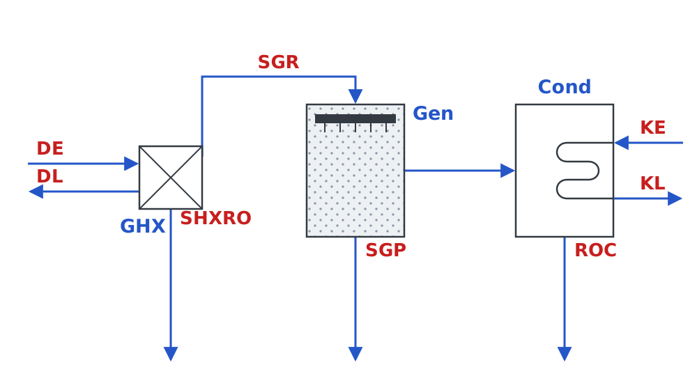
Notation (fixed terms; SHX and GHX are two different exchangers):
| Tag | Meaning |
|---|---|
| SHX | solution heat exchanger |
| GHX | generator heat exchanger (the external heating surface of this family) |
| DE / DL | drive heat entry / leave |
| SGR | rich solution entering the generator |
| SGP | weak solution leaving the generator |
| SHXRO | rich solution outlet of the solution heat exchanger |
| KE / KL | sink entry / leave (condenser cooling water) |
| ROC | refrigerant at the condenser outlet |
| SE / SL | source entry / leave (evaporator side; not in this fragment) |
Calculation table (draft)
Inputs (four givens): the generator outlet flow ṁsgp, the outlet concentration ξsgp, the condensing temperature Tcond, and the vapour flow ṁv,gc. Every other quantity is computed from the books in the table (marked “solve”); the numerical values of temperatures and enthalpies await the property basis. The relations between the state quantities — the flash equilibrium, how each enthalpy is taken and on what basis, the heat-transfer constraints on the two utility sides — are exactly the basis this table is missing; each will be filled in as the books are checked.
| Tag | Stream | ṁ (kg/s) | T (℃) | ξ (%) | h (kJ/kg) | Basis |
|---|---|---|---|---|---|---|
| DE | drive heat, in | solve | solve | — | solve | to follow |
| DL | drive heat, out | solve | solve | — | solve | to follow |
| SHXRO | rich solution, out of the SHX | solve | solve | solve | solve | to follow |
| SGR | rich solution, into the generator | solve | solve | solve | solve | to follow |
| SGP | weak solution, out of the generator | given | solve | given | solve | to follow |
| — | refrigerant vapour, generator → condenser (flow ṁv,gc) | given | solve | — | solve | to follow |
| ROC | refrigerant liquid, out of the condenser | solve | solve | — | solve | to follow |
| KE | heat sink, in (cooling water) | solve | solve | — | solve | to follow |
| KL | heat sink, out (cooling water) | solve | solve | — | solve | to follow |
One book per component (no heating inside the chamber; the heat input is booked on the GHX):
GHX: Qg = ṁsgr·(hsgr − hshxro) = ṁd·(hDE − hDL)
Gen (flash chamber): ṁsgr = ṁsgp + ṁv,gc, ṁsgr·ξsgr = ṁsgp·ξsgp, ṁsgr·hsgr = ṁsgp·hsgp + ṁv,gc·hv,gc
Cond: Qcond = ṁv,gc·(hv,gc − hroc) = ṁk·(hKL − hKE)
Note: the high-side pressure is fixed by Tcond, Pgen = Pref(Tcond). One condition is still missing to close the GHX book and fix Qg: either the drive side (ṁd with TDE, TDL) or the SHXRO temperature — one of the two, to be decided.
Status
Worked examples are being collected from the published models in this family and will be added case by case, each with its balance boundary, enthalpy basis and accounting side stated.